Technology Exchange
Induction soldering of antenna components
1. Introduction
1.1 Purpose of writing
The object described in this article is the antenna component induction soldering scheme V0.2 (hereinafter referred to as "this system"), through the description of the design ideas, the system architecture, and the collaboration between the subsystems that make up the system to meet the system Indicators, at the same time, provide the necessary foundation for the development of the requirements of each subsystem that composes the system, and the definition of the interface between the subsystems.
1.2 Terms, definitions and abbreviations
Antenna assembly induction welding scheme: This scheme makes plans for the brazing process of the antenna assembly of Aowei Communication Company, and proposes a simple and feasible manual welding scheme.
2. project overview
According to the requirements of the processing technology, the antenna assembly needs to be induction brazed. Figure 1 Photo of the finished antenna assembly.
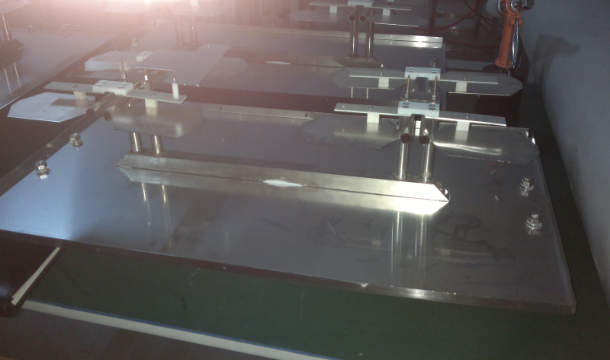 |
| Figure 1 Finished antenna assembly |
The overall frame of the entire system includes a high-frequency welding machine, three sets of positioning fixtures, three inductors and a cooling system.
3. design ideas
3.1 Consideration of the overall system framework
Currently, processing efficiency is not considered.
The entire antenna assembly includes 1 square tube, 4 risers, 4 straight tubes, and 8 wing antennas.
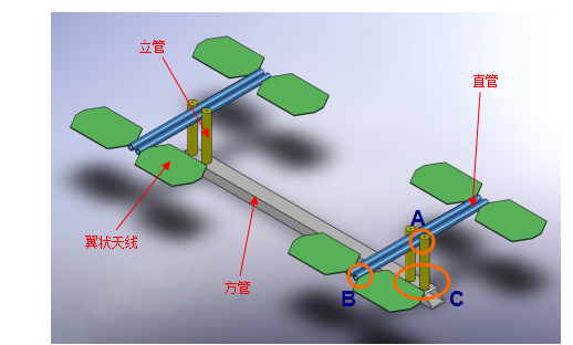 |
| Figure 2 Three-dimensional model of the antenna assembly to be welded |
It can be broken down into 4 independent antenna components, welded to a square tube base:
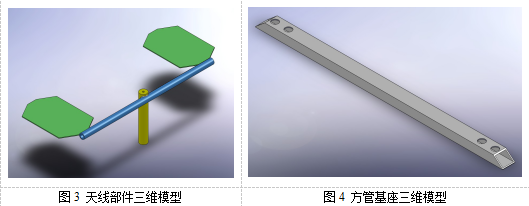
Three induction coils are used to weld the three welding positions A, B and C respectively.
3.2 Reliability considerations
In order to meet the system reliability requirements, consider the following aspects:
1. Life of mechanical system;
2. The system connection (including waterway and circuit) is reliable;
3. The accuracy of fixtures.
3.3 Heat source and sensor considerations
In order to meet the control requirements, the high-frequency machine adopts DIH-25 equipment, and the specific processing parameters are to be determined. According to the position of the welding seam, three different sensors are designed.
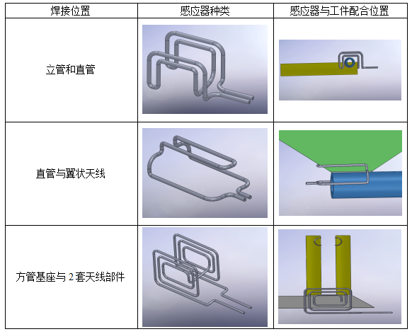
3.5 Tooling and fixture considerations
3.5.1 This set of tooling is generally divided into 3 independent toolings, corresponding to 3 welding stations;
3.5.2 All tooling adopts manual feeding and manual operation of the clamping device; (manual operation mainly operates handwheels, elbow clamps and other operating parts)
3.5.3 If the welding station requires the workpiece to be rotated 180 and then welded again, manual operation is also adopted.
3.6 Waterway considerations
The main function of the water circuit is: the internal cooling of the main machine and the extension of the welder adopts a circulating cooling method.
3.7 Workpiece cooling
Consider adopting air-cooling method to cool the welded workpiece, which can be considered by Aowei Communication.
4. structure description
4.1 System architecture description
This system consists of 6 parts including full digital welding machine, water chiller, welding tool A, welding tool B, welding tool C, and air-cooling mechanism.
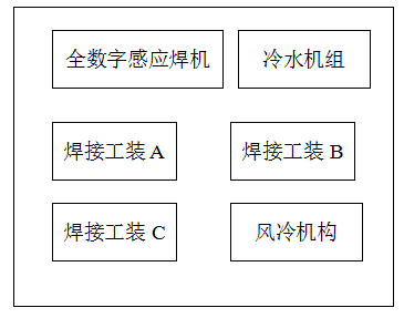 |
| Figure 5 System construction diagram |
4.2 Description of welding machine part
The welding machine adopts DIH-25 type all-digital induction heating equipment, and adopts a special multi-stage temperature control program for copper brazing during welding to fully guarantee the brazing rate.
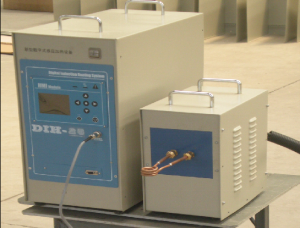 |
| Figure 6 Welder part |
4.2 Welding process description
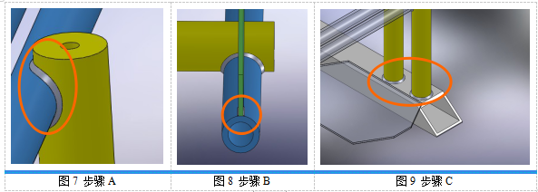
The entire antenna assembly can be divided into three welding steps:
Step A: Weld the riser and straight pipe, as shown in Figure 7;
Step B: Weld the straight tube and 2 wing antennas twice in succession, as shown in Figure 8;
Step C: Weld the square tube base and 2 sets of antenna components twice in succession, as shown in Figure 9;
4.3 Auxiliary equipment
The cooling of induction heating equipment can be equipped with a chiller, and the parameters of the chiller are determined according to its calorific value, and the cooling capacity is initially determined to be no less than 5 horses;
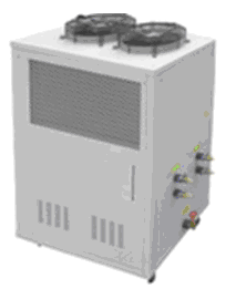 |
| Figure 10 Chiller |
4.4 Description of protection part
The protection part is the key to the reliable operation of the entire system. In order to avoid serious accidents, the protection part must be reliable. When the equipment fails or an abnormal situation occurs, the equipment control system operates in time (such as power failure), etc., and sends a corresponding alarm signal on the display device.
5. problem description
1. The sensor design should be carried out after obtaining the specific workpiece;
2. The fixture part needs to be further refined and considered.


 Scan and follow!